Freshlex LLC (should) architect the reliable multicast infrastructure for the putative John Carmack biopic, which will hit the internet in December of 2018. The first blog post discusses two of the enabling technologies, FCAST and ALC. This blog post discusses the three technologies that enable ALC: LCT, WEBRC and the FEC building block.
Reliable Multicast Building Block: LCT
LCT Description
Since the 70’s engineers have for the most part associated the transport layer of the Open Systems Interconnect (OSI) protocol stack with either Transmission Control Protocol (TCP) or the User Datagram Protocol (UDP). More recently, we have real time protocol (RTP) as a session layer for real time media. This blog post introduces a new transport layer protocol, layered coding transport (LCT).
LCT acts as a building block for ALC. LCT provides a transport layer service that, in concert with FEC and WEBRC allows ALC to be a massively scalable and reliable content stream delivery protocol for IP multicast networks. RMT WG designs LCT for multicast protocols and designs LCT to be compatible with WEBRC and FEC. LCT does not require any backchannel and works well with any LAN, WAN, Intranet, Internet, asymmetric NW, wireless NW or Satellite NW (RFC5651 9). LCT works best for at least multi-GB objects that are transmitted for at least 10s of seconds. Streaming applications benefit greatly from LCT. [RFC5651 4]
LCT Architecture Definition
LCT uses a single sender that transmits objects (interesting to receivers) via packets to multiple channels for some period of time. These channels split the objects into packets and associate the packets with the object using headers. LCT works with WEBRC to provide multiple-rate congestion control. Receivers join and leave LCT layers (via ALC channels) during participation in a session to reach their target reception rate (see WEBRC).
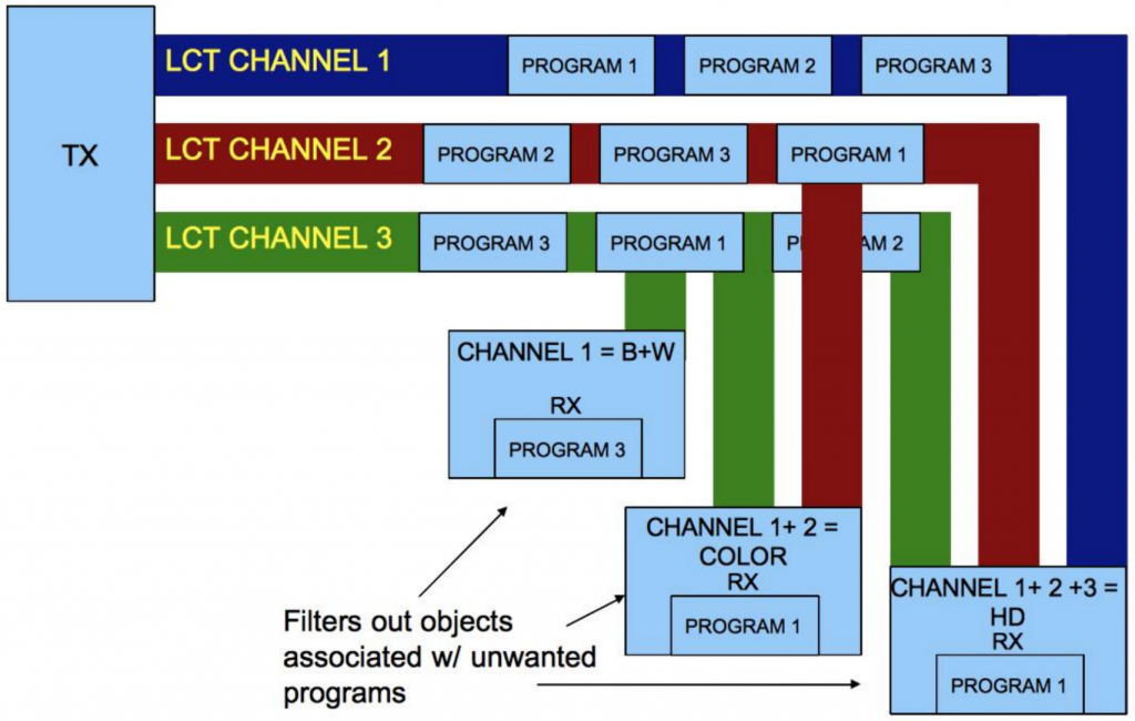
As the name suggests, LCT uses layered coding to produce a coded stream of packets that LCT partitions into ordered sets of packets. The FEC building block codes the packets for reliability. For streaming media applications, layering allows variable transfer speeds and by extension image quality to RX with arbitrary NW capacity. The best example of LCT follows.
Imagine a web TV application split into three layers. A RX that joins the first channel would receive a black and white picture. An RX that had more capacity would join the first and second channel and receive a color picture. An RX with transparent capacity would be able to join all three layers, and receive a HD color picture. The key to this example is that the sender does not duplicate any data between layers. The RX joins successive layers to receive a higher quality picture at the cost of using more bandwidth. [RFC5651 6]
LCT Operations
The WEBRC building block sends packets associated with a single session to multiple LCT channels at rates computed to optimize multiple-rate congestion control (RFC3738 3). The receivers join one or more channels according to the NW congestion. The WEBRC building block provides LCT with information for the CCI field, which is opaque to LCT (RFC5651 16). The FEC building block codes the packets that LCT sends to channels for reliability.
On the RX side, the RX must first join an LCT session. The RX must obtain enough of the session description parameters to start the session. Once the RX has all the session description parameters the RX begins to process packets. The RX must identify & de-multiplex the packets associated the LCT session. Each LCT session must have a unique Transport Session Identifier (TSI). The LCT session scopes the TSI by the (Sender IP Address, TSI) pair. LCT stamps each packet’s LCT header with the appropriate TSI. [RFC5651 25-26]
The RMT WG designed LCT for best effort (BE) service. BE service does not guarantee packet reception or packet reception order. BE service does not provide support for reliability or flow/ congestion control. LCT does not provide any of these services on its own. ALC, however, uses LCT along with FEC and WEBRC to provide reliable, multi-rate congestion controlled layered transport. [RFC5651 27]
Reliable Multicast Building block: WEBRC
WEBRC Description
As per RFC 2357, the use of any reliable multicast protocol in the Internet requires an adequate congestion control scheme. Furthermore, ALC must support RFC3738, the Wave and Equation Based Rate Congestion Control (WEBRC) Building Block (RFC5775 10). WEBRC provides multiple rate congestion control for data delivery. Similar to FCAST, ALC, LCT and multicast FEC, the RMT WG designs WEBRC to support protocols for IP Multicast. In the spirit of massive scalability, WEBRC requires no feedback and uses a completely receiver driven congestion control protocol. WEBRC enables a single sender to deliver data to individual receivers at the fastest possible rate, even in a highly heterogeneous network architecture. In other words, WEBRC dynamically varies the reception rate of each RX independent of other receivers (RFC3738 1). WEBRC competes fairly with TCP and similar congestion control sessions (RFC3738 4).
WEBRC Architecture Definition
A single sender transmits packets to multiple channels. The sender designates one channel as the base channel, the remaining are called wave channels. Each channel starts off at a high packet rate, after each equal-spaced period of time, the packet rate of that channel reduces until the channel is quiescent. A channel’s cycle from full rate to quiescence takes a configurable number of periods, by default their aggregate summing to a long duration of time (several minutes). At the end of each period, the RX joins or leaves channels depending on if the aggregate of the current TX rates allows the RX to reach its target RX rate. At the end of each period the RX orders each wave channel into layers, based on their TX rates (the higher the rate, the higher the layer). The designation of wave channel to a layer, therefore, varies cyclically over time. Once joined, an RX stays with a channel until that channel becomes quiescent. [RFC3738 8]
A key metric for each receiver, therefore, is the target reception rate. The target reception rate drives the number of layers (and by extension, channels) that a receiver must join. The RX measures and performs calculations on congestion control parameters (e.g. the average loss probability and the average RTT) and makes decisions on how to increase or decrease its reception rate based on these parameters. The RX based approach of WEBRC suits itself to protocols where the sender handles multiple concurrent connections and therefore WEBRC is suitable as a building block for multicast congestion control. An RX with a slow connection does not slow down RX with faster connections. [RFC3738 13-23]
WEBRC Operations
When WEBRC receives packets from ALC, WEBRC first checks to see that the packets belong to the appropriate session before applying WEBRC. ALC uses LCT, so WEBRC looks to the LCT header to find the (sender IP address, TSI) tuple that denotes what session a received packet belongs to (RFC5651 12). The multicast network identifies a channel to receivers via a (sender IP address, multicast group address) pair, and the receiver sends messages to join and leave the channel to the multicast group address. When the RX initiates a session, it must join the base channel. The packets on the base channel help the RX orient itself in terms of what the current time slot index is, which in turn allows the RX to know the relative rates on the wave channels. The RX orders these wave channels into layers, from lowest to highest rates. The RX remains joined to the base channel for the duration of its participation in the session. [RFC3738 8]
As mentioned earlier, the lowest layer has lowest rate and highest layer has highest rate. Each time a wave channel becomes active, it becomes the highest layer. At the end of each time slot the lowest-layer wave channel deactivates and all channels move down a layer. A RX always leaves the lowest layer when it deactivates.
After joining a session, the RX adjusts its rate upwards by joining wave channels in sequence, starting with the lowest layer and moving towards the highest. The rates on the active wave channels are decreasing with time so the receiver adjusts its rate downward simply by refraining from joining additional wave channels. The layer ordering among the channels changes dynamically with time so the RX must monitor the Current Time Slot Indicator (CTSI).
Once the receiver joins a wave channel, the receiver remains joined to the wave channel until it deactivates (RFC3738 8). The following diagram illustrates the relationship between wave channels, layers and target reception rate.
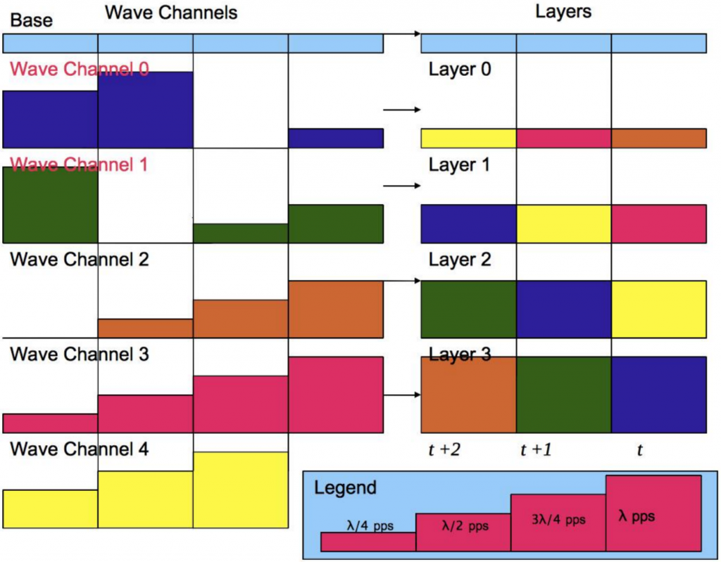 In the above figure, assume the receiver wants a target rate of 7λ/4 packets per second (pps). This means the receiver must join the base (λ/4pps), layer 0 (λ/4pps), layer 1 (λ/2pps) and layer 2 (3λ/4pps). The receiver joins layers by joining underlying channels, sending joins and leaves to their respective multicast addresses. We see in the figure that for time t, layer 2 contains wave channel 4, layer 1 contains wave channel 3 and layer 0 contains wave channel 2. The receiver leaves channel 1 (which is now quiescent). The receiver stays joined to the base and wave channels 3 and 2. The receiver sends a join to wave channel 4. At time t+1, the layers change again. The receiver stays joined to the base, 4 and 3. The receiver leaves channel 2 and joins channel 0. For time t+2, the receiver stays joined to the base, 0 and 4. The receiver leaves channel 3 and joins channel 1.
Reliable Multicast Building Block: FEC
FEC Building Block Description
Content Delivery Protocols (CDP) have many options available to them to increase reliability. We’ll first read about two non-forward error correction (FEC) based options: automatic request for retransmission (ARQ) and data carousels. First, consider ARQ. If an ARQ receiver does not receive a packet or receives a corrupted packet, the receiver asks the sender to re-transmit the packet. ARQ therefore, requires a back channel and does not scale well for one to many CDP. Using ARQ on one to many CDP sets the architecture up for feedback implosions and “NACK of death” (imagine 1e+7 receivers simultaneously detecting dropped data and asking for a re-transmission). In addition, in a network where different receivers have different loss patterns, ARQ wastes resources. RX would need to wait for the re-transmissions of packets that other receivers lost, even if the RX already have those data. [RFC5052 2]
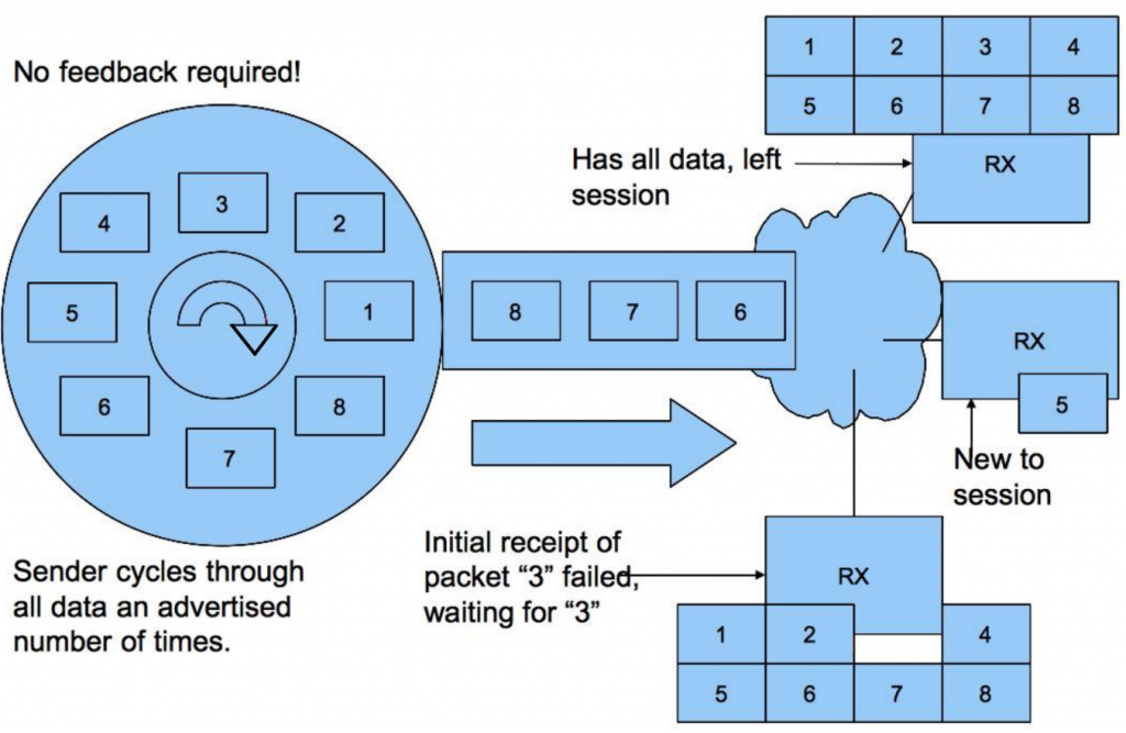
A data carousel solution partitions objects into equal length pieces of data (source symbols), puts them into packets and cycles through and sends these packets. Each RX receives the packets until they have a copy of every packet. While the data carousel solution requires no back channel, if an RX misses a packet, the RX has to wait on Carousel until it's sent again. [RFC6968 8]
RFC 3454 describes, therefore, how to use FEC codes to augment/ provide reliability for one-to-many reliable data transport using IP multicast. RFC 3454 uses the same packets containing FEC data to simultaneously repair different packet loss patterns at multiple RX. [RFC3453 4]
FEC has multiple benefits for our FCAST/ALC architecture. FEC augments reliability and overcomes erasures (losses) and bit level corruption. The primary application of FEC to IP multicast, however, is an erasure code since the IP multicast NW layers detect (bit level) corrupted packets and discard them (or the transport layers will use packet authentication to discard corrupted packets) (RFC3453 3).
FEC Operation
The data source inputs into FEC some number k of equal length source symbols. The FEC encoder then generates some number of encoding symbols that are of the same length as the source symbols. The packets are placed into packets and then sent. On the receiving side, the RX feeds the encoded symbols into a decoder to recreate an exact copy of the k source symbols. ALC can use block or expandable FEC codes for the underlying FEC building block. [RFC5775 11]
With a block encoder, we input k source symbols and a constant number n. The encoder generates a total of n encoding symbols. The encoder is systematic if it generates n-k redundant symbols yielding an encoding block of n encoding symbols in total composed of the k source symbols and the n-k redundant symbols. With a block encoder, any k of the n encoding symbols in the encoding block is sufficient to reconstruct the original k source symbols. [RFC3453 5-6]
An expandable FEC encoder takes input of k source symbols and generates as many unique encoding symbols as requested on demand. At the receiver side, any k of the unique encoding symbols is enough to reconstruct the original k source symbols. [RFC3453 7]
Conclusion
This post discusses three technologies that enable ALC for reliable multicast: LCT, WEBRC and the FEC building block. The next blog post discusses an Architecture that integrates all of the enabling technologies.
Bibliography
[RFC3453] Luby, M., Vicisano, L., Gemmell, J., Rizzo, L., Handley, H. and J. Crowcroft, “The Use of Forward Error Correction (FEC) in Reliable Multicast”, RFC 3453 December 2002.
[RFC3738] Luby, M. and V. Goyal, “Wave and Equation Based Rate Control (WEBRC) Building Block”, RFC 3738, April 2004.
[RFC5651] Luby, M., Watson, M. and L. Vicisano, “Layered Coding Transport (LCT) Building Block”, RFC 5651, October 2009.
[RFC5775] Luby, P., Watson, P. and L. Vicisano, “Asynchronous Layered Coding (ALC) Protocol Instantiation”, RFC 5775, April 2010.
[RFC6968] Roca, V. and B. Adamson, “FCAST: Scalable Object Delivery for the ALC and NORM Protocols”, RFC 6968, July 2013.
[RFC5052] Watson, M., Luby, M. and L. Vicisano, “Forward Error Correction (FEC) Building Block”, RFC 5052, August 2007.